REPAIRING KENWOOD TM-241E
INTRODUCTION
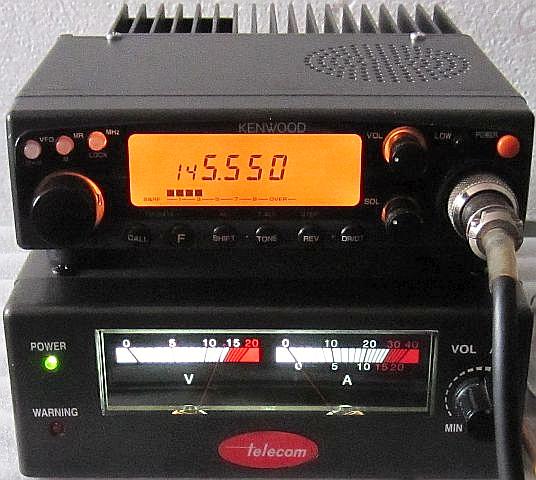
Under the motto: "We can't do anything with it, maybe it's something for you?" a KENWOOD 241E 2m FM transceiver without a microphone came into my possession. All screws from the top and bottom cover were missing, only one screw held the top in place.
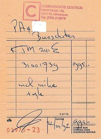
Included was the original manual and a purchase receipt! It can be seen that in 1992, 995.00 guilders (ƒ995.00) was not cheap for the set.
This is nothing compared to even more "abracadabra."
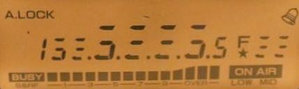
At home it was connected to a power supply and turned on. The display seemed normal and when a Kenwood microphone was connected, the set actually came to life. Even QSOs were made with it, but after a while, "abracadabra" appeared on the diplay. Fortunately, transmitting and receiving system still worked.
VERY COMMON DISPLAY PROBLEM
Information from the Internet showed that with this transceiver the display problem is often noted and it manifests after a while. How the problem can been tackled is extensive published on the internet, so this article will not explained in detail how the device should be disassembled, but a few problems are highlighted.
From the inside one could see hat a previous owner had already worked on the repair, but apparently without a positive result.
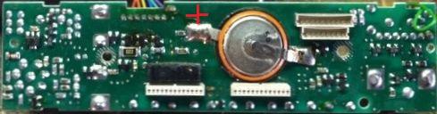
BACK-UP BATTERY
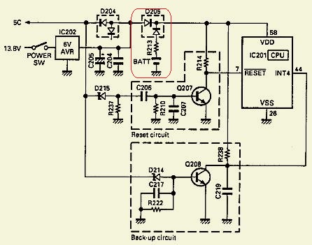
Because the device still needs to be opened, a new backup battery for the memory could also be replaced. This is mounted on the back of the display board. The manual states that such a battery usually lasts for 5 years and should only be replaced by an authorized KENWOOD dealer or service department. If you experience how much work that is, then repairing probably costs half of the purchase price.
The battery still had the full voltage and apparently was replaced. Onl...y the poles were reversed, so it was feared that the memory was defective.
Later it turned out that it could not cause any damage because a diode D206 was connected in series with the battery. Not a bad idea (fig») of the designer.
 This is how the battery should be mounted.
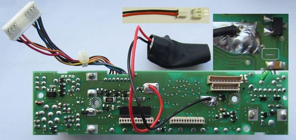
On my PCB you can clearly see a minus sign, but on the Internet PCB's are shown with a different track pattern where the minus sign is missing.
In order to avoid all that replacement work in the future, the battery is fitted with extension wires as with other publications, but equipped with connectors and insulated with heat shrink.
LOOSE CONNECTOR
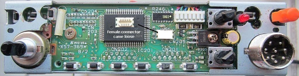
When disconnecting two boards, the female surfase mount connector of this (fig») control board (located behind the display) was complete off the control board and stuck on the male connector of the display board. When both boards were mounted, the femail connector was pressed against the control board and made occasional contact with the 9 tiny tracks, so that the display regularly failed and showed abracadabra.
It could be seen that a previous owner had soldered to the connector. It was not resolving and that is understandable, because it is a lot of trouble to solder those narrow close together tracks. Moreover, on that part of the PCB the manufacturer has soldered with insufficient soldering fluid, especially cold welding occurs under the connector.
After it was determined that no other cold welds existed, the detached culprit was carefully soldered to the PCB and the set assembled again.
Everything worked perfectly and the memory was also filled with various repeaters.
Until one day, after a QSO was made and the device was still on, I was in another room to do something. When I returned, the display was on BLACK, but the set still worked!
Resetting didn't help and the set was dismantled again. All print tracks and welds were checked even more accurately than the last time. Especially the connector got a lot of attention and under a incidence of light, some tracks didn't seem to be stuck. So I did a resoldering, assembled the transceiver and with my toes curled switched on power. The display was crystal clear again and everything worked properly!
CONCLUSION
Because two boards are connected to each other with these mating connectors, screwing boards to the set will result in mechanical stress that loads the tracks. If the transceiver is also installed in a car or pick-up, it can be expected that a moving vehicle adds vibrations with even more mechanical tension. It is not inconceivable that the cause of the display problem is mainly related to these connectors.
FRONT PANEL
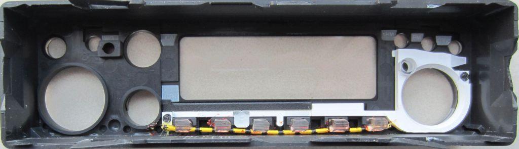
The buttons in the front panel are prevented from falling out by a strip of foam rubber. The strip deteriorates is less resilient and sticks. Keeping the buttons in place can be solved by inserting a piece of wire in the slot of the removed foam.
POWERMODULE
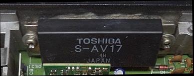
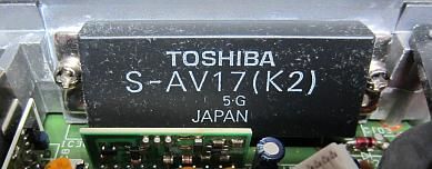
The ouput of the S-AV17 power module can be increased to more than 50 W if it is set with potentiometer R4 (APC), but that is not recommended. Especially because Kenwood has not applied any conductive grease between the cooling block and the module. This is strange because the surface of the cooling block is not smooth.
Someone already supplied my S-AV17(K2) with the grease.
Even with 50 W and a warm environment such as in a car during hot summers, there are notifications about a failing module.
At a room temperature of 17ºC and a constant carrier of more than 5 minutes, the cooling block became quite warm.
When tested with a small 4 × 4 × 3 cm fan against the back of the cooling block, it turned out to have a surprising cooling capacity.
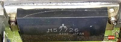
A replacement for the S-AV17 is apparently a MITSUBISHI power module M57726.
This repaired TM-241E delivered:
| 145 MHz, 50 Ohm dummy load, 13.8 Volt | |
| Standby | 412 mA |
| 50 Watt | 8.60 Amp |
| 16 Watt | 4.75 Amp |
| 7.5 Watt | 3.70 Amp |
Keep in mind that with a more complex 50 Ohm load (antenna) the current can increase to 10 Amp.
MC-44E CHINESE CLONE
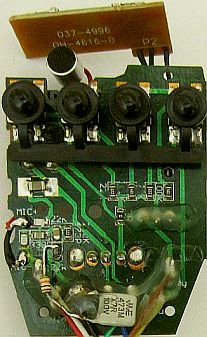
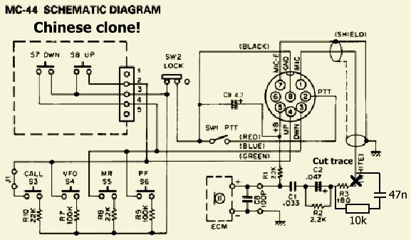
It has been said before, there was no microphone. On the internet, including shipping, a Chinese clone of the MC-44E type was found for € 10.15.
Given that amount, it would not be a disaster if it turned out to be a bad buy.
Fortunately all the buttons worked well, but the modulation was too strong and with my voice it sounded quite bassy. It is not a dynamic microphone, but an electret type.
After some experimentation, an acceptable result was obtained by applying a 10 kOhm resistor and a 47 nF capacitor. Both were mounted in series with R2 and C2 by cutting the print track from R3 to the microphone wire.
Incidentally, R3 (180 ohms) in the diagram was by the factory installed with only 22 ohms.
![]()
![]()